Table of Contents
Metal Removal Rate Calculator
how to calculate MRR ?
The Metal Removal Rate is calculated by multiplying the area of the chip’s cross-section by the linear velocity in the direction perpendicular to it.
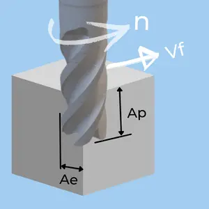
Let’s look at a simple milling application as an example:
- The chip Area is Ap x Ae
- The Perpendicular Speed is the table feed (Vf).
(In a full plunging operation, the chip area would be π x D2 / 4, and the speed would be feed in the spindle’s direction.)
The result is multiplied by a constant depending on the units used (Metric/Inch) to get the final result in either cubic inches or cubic centimeters.
\large MRR =
\\
\large \text {Chip Area} \times
\\
\large \text { Perpendicular Speed} \times
\\
\large \text { Unit Constant}
\end{matrix} \)
Metal Removal Rate Formulas
( For detailed explanations, check the sections below on each application)
| Application | Metric [Cm3] | Inch [Inch3] | ||
|---|---|---|---|---|
Milling |
\(\LARGE \frac {A_p \times\, A_e \times\, V_f }{1,000}\) |
\( \large A_p \times A_e \times V_f \) |
||
Turning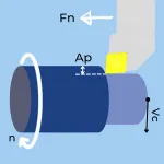 |
\( \large A_p \times F_n \times V_c \ \) |
\( \large A_p \times F_n \times V_c\ \times 12 \) |
||
Drilling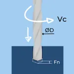 |
\(\LARGE \frac {D \times\, F_n \times\, V_c }{4}\) |
\( \large D \times F_n \times V_c\ \times 3 \) |
||
Grooving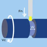 |
\( \large W \times F_n \times V_c \ \) |
\( \large W \times F_n \times V_c\ \times 12 \) |
||
Units used in the above table:
- Ap, Ae, D, W – mm or Inch
- Vf – m/min or inch/min
- Vc – m/min or feet/min (SFM)
- Fn – mm/rec or Inch/rev
- MRR – Metal Removal Rate CM3/min or Inch3/min
MRR formulas explained
As explained in the introduction, Metal Removal Rate is defined as:
\large MRR =
\\
\large \text {Chip Area} \times
\\
\large \text { Perpendicular Speed} \times
\\
\large \text { Unit Constant}
\end{matrix} \)
We will break down this basic formula for the main machining applications
Metal Removal Rate in Milling

- Ap – Axial depth of cut in mm or inches.
- Ae – Radial depth of cut in mm or inches.
- Vf – Table Feed in m/min or inches/min
- MRR – Metal Removal Rate in CM3/min or Inch3/min
\(
\begin{matrix}
&\text{Chip Area}& & \text {perpendicular Speed} & & \text {Unit Constant}\\
\large MRR = &\overbrace{A_p\,\times\,A_e} &\times&\overbrace{V_f} &\times&\overbrace{K}
\end{matrix}
\)
- In imperial units, all the parameters are in Inches; therefore, K=1 is used to get the final result in Inch3.
- In metric units, Ap and Ae are in mm, while Vf is in meters. therefore, K=0.001 get the result in Cm3.
\(
\large MRR\,[\frac {Cm^{3}}{min}] = \LARGE \frac{A_p\,\times\,A_e\,\times\,V_f}{1,000} \\
\)
\(
\large MRR\,[\frac {Inch^{3}}{min}] = A_p\,\times\,A_e\,\times\,V_f
\)
Metal Removal Rate in Turning
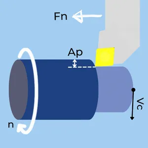
- Ap – Depth of cut in mm or inches.
- Fn – Feedrate n in mm or inches.
- Vc – Cutting Speed in m/min or feet/min (SFM).
- MRR – Metal Removal Rate in CM3/min or Inch3/min
\(
\begin{matrix}
&\text{Chip Area}&&\text {perpendicular Speed}&&\text {Unit Constant}\\
\large MRR = &\overbrace{A_p\,\times\,F_n}&\times&\overbrace{V_c} &\times&\overbrace{K}
\end{matrix}
\)
- In imperial units, the speed is given in SFM and K equals12 to convert the speed into Inches/min and get the final result in Inch3.
- In metric units, K=1 to get the result in Cm3
\(
\large MRR\,[\frac {Cm^{3}}{min}] = A_p\,\times\,F_n\,\times\,V_c
\)
\(
\large MRR\,[\frac {Inch^{3}}{min}] = A_p\,\times\,F_n\,\times\,V_c\,\times\,12
\)
Metal Removal Rate in Drilling
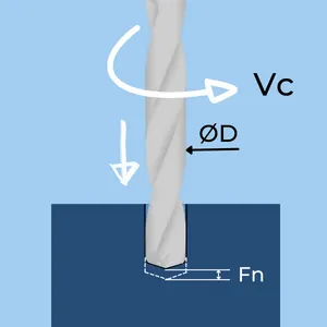
- D – Drill diameter in mm or inches.
- Fn – Feed per Revolution in mm or inches.
- Vc – Max Cutting Speed in m/min or feet/min (SFM).
- MRR – Metal Removal Rate CM3/min or Inch3/min
\(
\begin{matrix}
&\text{Chip Area}&&\text {perpendicular Speed}&&\text {Unit Constant}\\
\large MRR = &\overbrace{D\,\times\,F_n\,\times\,0.5}&\times&\overbrace{V_c\,\times\,0.5} &\times&\overbrace{K}
\end{matrix}
\)
- The chip area is the radius (D/2) of the drill times the feed per revolution.
- The speed starts with zero at the center of the drill and reaches its maximum at the OD. Therefore, we use the average speed, which is Vcmax/2.
- In imperial units, the speed is given in SFM, and K equals12 to convert the speed into Inches/min and get the final result in Inch3.
- In metric units, K=1 to get the result in Cm3
\(
\large MRR\,[\frac {Cm^{3}}{min}] = \LARGE \frac{D\,\times\,F_n\,\times\,V_c}{4} \\
\)
\(
\large MRR\,[\frac {Inch^{3}}{min}] = D\,\times\,F_n\,\times\,V_c\,\times\,3
\)
Metal Removal Rate in Parting and Grooving
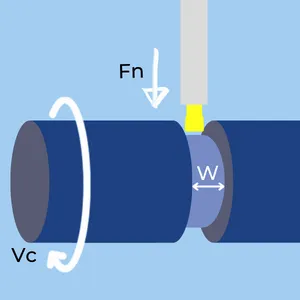
- W – Width of Groove in mm or inches.
- Fn -Feedrate in mm or inches.
- Vc – Cutting Speed in m/min or feet/min (SFM).
- MRR – Metal Removal Rate in CM3/min or Inch3/min
\(
\begin{matrix}
&\text{Chip Area}&&\text {perpendicular Speed}&&\text {Unit Constant}\\
\large MRR = &\overbrace{W\,\times\,F_n}&\times&\overbrace{V_c} &\times&\overbrace{K}
\end{matrix}
\)
- In imperial units, the speed is given in SFM, and K equals12 to convert the speed into Inches/min and get the final result in Inch3.
- In metric units, K=1 to get the result in Cm3
\(
\large MRR\,[\frac {Cm^{3}}{min}] = W\,\times\,F_n\,\times\,V_c
\)
\(
\large MRR\,[\frac {Inch^{3}}{min}] = W\,\times\,F_n\,\times\,V_c\,\times\,12
\)
What is MRR used for ?
The Metal Removal Rate is used for two main purposes:
1) Estimating the machine power consumption for a given set of machining conditions
Each raw material has a Specific Cutting Force property, designated by Kc. The constant is in pressure units (Force per Area) and is usually listed in Mpa (N/mm2) or N/Icnh2. The specific cutting force indicates how much force is needed to shear a chip from the raw material, and multiplying it with the Metal Removal Rate yields the required Machining Power. This method of machining power calculation is an indirect estimation; however, due to its simplicity and decent accuracy, it is the most widely used way to compute machining power.
2) Comparing the productivity of two machining processes
Suppose we need to mill a cube in the dimensions of 1″ X 1″ X 1″ with a 0.5″ diameter endmill. Two workers suggest different approaches to perform the task.
- Worker #1 r suggests using a 1/2″ 4 flute endmill with cutting conditions: Ap=0.5″, Ae=0.25″, fz=0.004 Inch/rev and VC=300 SFM.
- Worker #2 suggests using a 1/2″ 6 flute endmill with cutting conditions: Ap=0.5″, Ae=0.1″, fz=0.005 Inch/rev and Vc=350 SFM.
To evaluate which options yield the best productivity, we can compare the MRR of both options:
Worker #1:
Worker #2:
By comparing the MRR value of the options, we can see that the approach suggested by worker #1 provides higher productivity.


