What Is Chip Thinning?

In a “Classic” milling operation, the Radial Depth of Cut [Ae] is greater or equal to the cutter’s radius, and the angle is 90°. In such cases, The Chip Load equals the Feed Per Tooth.
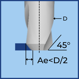
When the Radial Depth of Cut [Ae] is smaller than the cutter’s radius, OR the cutter’s shape is not 90° (Chamfer, Ballnose, etc.), The Chip Load is smaller than the Feed per Tooth. This reduction in Chip Load is called “Chip Thinning”.
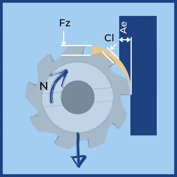
The relation between Chip Load [CL] and the Feed Feed Per Tooth [FZ[ is represented by the Chip Thinning Factor [CTF]
\( \large CTF = \frac {\huge F_z}{\huge C_l} \)Why Is Chip Thinning Important?
Chip Thinning allows dramatic productivity gain since you can multiply the Feed by the Chip Thinning Factor while keeping the Chip Load within the recommended range!
Table of Contents
Radial Chip Thinning Calculator
Axial Chip Thinning Calculator
Chip Thinning Explained
Chip Load (Maximum chip thickness) is one of the most important parameters for achieving a productive and reliable milling process. Effective cutting will only be obtained when the Chip Load is in the correct range appropriate for a specific cutter. The best practice is to get it from the supplier’s catalog, but if you don’t have it, you can use our Chip Load Calculator, giving you a good starting point.
- A Chip Load (Maximum Chip Thickness) that is too low can cause poor performance due to rubbing, resulting in poor tool life or chip formation.
- A Chip Load that is too high will overload the cutting edge, leading to fast wear and even breakage.
The Chip Thinning Factor (CTF) enables you to calculate the Feed Per Tooth that will yield the desired Chip Load.
There are two Chp Thinning Factors:
- RCTF – Radial Chip Thinning Factor.
- ACTF – Axial Chip Thinning Factor.
The two factors are independent and should be applied one on top of the other:
\( \large CTF = RTCF \times ACTF \)
\( \large F_z= Recomended \ Chip \ Load * CTF \)
Radial Chip Thinning
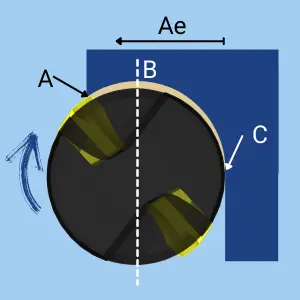
- In a milling operation, the Chip Thickness varies between the point of entry (A) and the Point of Exit (C).
- At the Point of Exit (C), the thickness is always Zero.
- When the radial depth of cut (Ae) is larger than the cutter’s radius, the chip thickness starts with a certain value. It gradually grows unit it reaches its maximum thickness at the cutter’s center (B). At this point, the Maximum Chip Thickness equals the Feed Per Tooth.
- After that, the Chip Thickness gradually gets smaller until it reaches zero at the exit point (C).
CONCLUSION
* When Ae>=R (Cutter Radius) the Maximum Chip thickness is constant and is equal to the Feed per tooth.
* When Ae<R, the Maximum Chip thickness depends on the radial depth of Cut (Ae) and will always be smaller than the Feed Per Tooth.
* THE PHENOMENON OF REDUCTION IN THE MAXIMUM CHIP THICKNESS RELATIVE TO THE FEED PER TOOTH IS CALLED CHIP THINNING.
* WHEN SUCH A REDUCTION IS THE RESULT OF THE RADIAL DEPTH OF CUT, IT IS CALLED RADIAL CHIP THINNING.
Radial Chip Thinning Formulas

- Fz – Feed Per Tooth. The goal is to calculate the Fz that will create the recommended Chip Load.
- Cl – Chip Load. (Recommended by the tools supplier or from our Chip Load Calculator).
- Ae – Radial Depth of Cut.
- D – Cutter Effective Diameter.
- RCTF – Radial Chip Thinning Factor. The ratio between the Chip Load (Cl) and the Feed per Tooth (Fz)
\( \large F_z = RCTF \times C_l \)
Axial Chip Thinning

When the cutting edge approaches the material at a 90° angle, the Feed Per Tooth [Fz] Equals the Chip Load (Chip Thickness) [Cl]

When the cutting edge approaches the material at an angle smaller than 90°, the Feed Per Tooth [Fz] is greater than the Chip Load (Chip Thickness) [Cl]

The same principle also works on round cutting edges (Such as ballnose and milling cutters with round inserts). In such cases, the approach angle is the tangent to the cutting edge’s radius at the deepest point of engagement.
Important Remark: The Term “Axial Chip Thinning” is misleading. It comes from the fact that in a round shape cutter the chip thinning is a function of the axial depth. However, As explained above, it is actually a result of the approach angle. In feedmills and chamfer cutters, the axial depth has no effect on the chip thickness. A more appropriate term would be “Approach Angle Chip THinning”. However, to be consistent with the common nickname we refer to it as “Axial Chip Thinning”.
CONCLUSION
* Since the cutting edge is “feeling” is the Chip Load (And not the Feed Per Tooth), The Feed can be increased until the maximum recommended chip load is reached.
* The factor by which the feed can be multiplied is called the Axial Chip Thinning Factor [ACTF].
Axial Chip Thinning Formulas
Chamfer Cutters
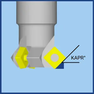
- Fz – Feed Per Tooth. The goal is to calculate the Fz that will create the recommended Chip Load.
- Cl – Chip Load. (Recommended by the tools supplier or from our Chip Load Calculator).
- KAPR – Approach Angles
- ACTF – Axial Chip Thinning Factor. The ratio between the Chip Load (Cl) and the Feed per Tooth (Fz)
\( \large F_z = ACFT \times C_l \)
Ballnose Cutters
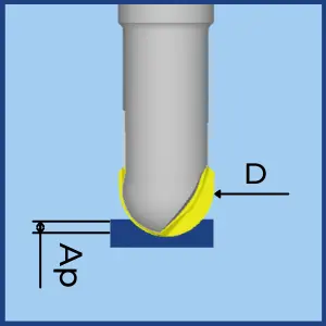
- Fz – Feed Per Tooth. The goal is to calculate the Fz that will create the recommended Chip Load.
- Cl – Chip Load. (Recommended by the tools supplier or from our Chip Load Calculator).
- Ap– Depth Of Cut
- D – Ball Diameter.
- ACTF – Axial Chip Thinning Factor. The ratio between the Chip Load (Cl) and the Feed per Tooth (Fz)
\( \large F_z = ACFT \times C_l \)
Round insert Cutters

- Fz – Feed Per Tooth. The goal is to calculate the Fz that will create the recommended Chip Load.
- Cl – Chip Load. (Recommended by the tools supplier or from our Chip Load Calculator).
- Ap– Depth Of Cut
- IC – Insert size (Inscribed circle.)
- ACTF – Axial Chip Thinning Factor. The ratio between the Chip Load (Cl) and the Feed per Tooth (Fz)
\( \large F_z = ACFT \times C_l \)


