What is a cutting edge (In machining)?
Cutting edge refers to the “Micro-Geometry” of the cross-section at the tip of the inserts that engages with the workpiece material. Although the length of the cross-section could be less than 1 mm it has an enormous effect on the performance.
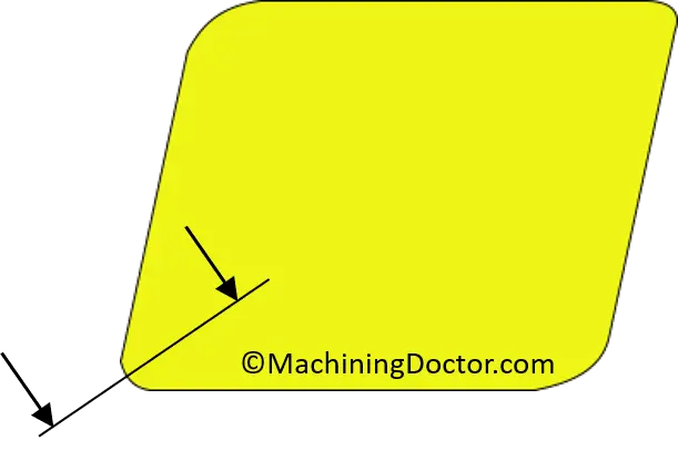
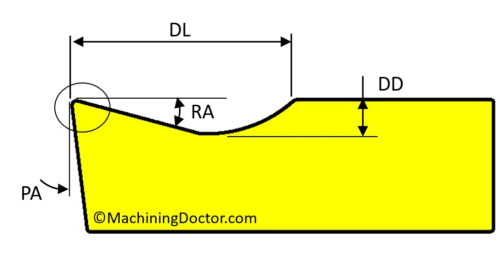
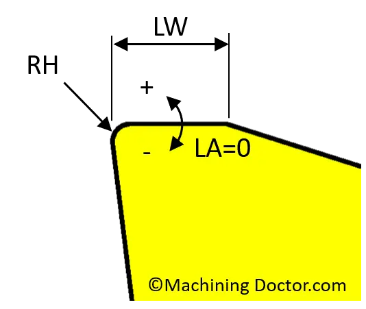
Cutting Edge Parameters:
- DL – Deflector Length / DD – Deflector Depth
- RA – Rake Angle / PA – Periphery Angle
- RH – Honing Radius
- LW – Land Width / LA – Land Angle
Deflector (DL – Deflector Length / DD – Deflector Depth)
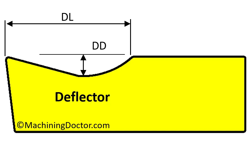
The main purpose of the deflector is to break the chips.
Tighter Deflector: A deflector with a smaller DL and deeper DD has a more aggressive effect on the chips. It will enable to break chips at lower feed rates and thus is more suitable for finish applications. Another use for a tight deflector is to break chips when machining soft materials. The downside is that much more heat is generated, and at higher feedrates, the chips come out “burned” and the tool-life is shorted.
Open Deflector: A deflector with a larger DL and shallower DD gives the chips more space to flow and generates less heat. This is good for short chipping materials and at higher feedrates, where the chips will break without an aggressive deflector.
Rake Angle (RA)
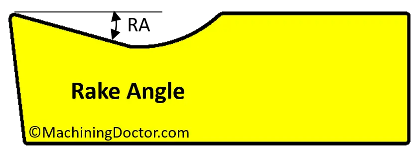
An insert with a bigger RA and/or PA is considered a more “Positive” insert. More positive inserts exsert lower force on the workpiece. There several reasons to opt for a more positive geometry.
- When machining small workpieces or thin walls.
- Machining with a tool that has a long overhang.
- When machining materials that “like” sharper geometries like supper-alloys and non-ferrous alloys.
Cutting edge Sharpness
The next 3 parameters, RH, LW, and LA all control the sharpness of the cutting edge. A sharper edge provides a smoother cut, produces less heat, and exerts a smaller force on the workpiece. On the other hand, a sharper edge is weaker, more sensitive to microbreaks and deformation. The right balance between toughness and sharpness of the cutting edge must be optimized according to the workpiece material and application to achieve the best results.
RH – Honing Radius
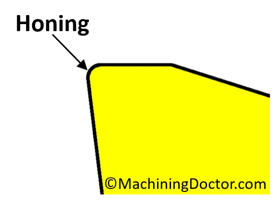
Honing is a process that rounds the tip of the cutting edge, typically to a radius size is between 0.001-0.003″ (0.03-0.08 mm) . It is usually done with sandblasting. When an insert comes out of the production line it has a burr from the connecting line of the die set. The honing process eliminates the burrs. When inserts are ground the cutting edge comes out of the process with an RH of zero (Up Sharp). In most cases the insert will be honed also after grinding otherwise the cutting edge will be too sharp and very sensitive to breakages.
Typical honing values:
- Small Honing 0-0.01 mm – Machining small workpieces or thin walls. Can be found on small ground and positive turning inserts and solid carbide endmills.
- Average Honing 0.03-0.05 mm – A common honing size for finish and medium applications in turning and milling.
- Large Honing 0.06-0.08 mm – Used for heavy application or interrupted cuts.
Land
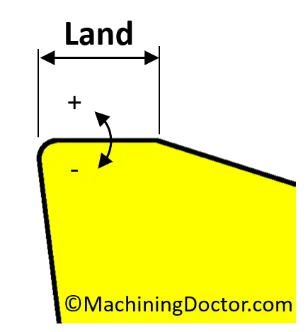
A “Land” is a small flat area, typically 0.002-0.02″ (0.05-0.5 mm) long that connects between the tip of the cutting edge to the rake angle.
LW – Land Width:
A bigger land width increases the toughness of the cutting edge and it’s ability to withstand blows. The downside is higher cutting forces.
LA – Land Angle:
- LA of zero is a neutral land which is very common.
- A positive land angle increases the sharpness but recuses the toughness of the cutting edge.
- A negative land angle increases the toughness at the expense of sharpness. It is common to find negative lands when machining cast iron or in very heavy applications.


