National Pipe Thread is an American standard defined in ASME B1-20.1 The most popular series is Tapered Pipe Thread (NPT). However, other series, such as NPTSC and NPTR, are also defined by this document.
The Jargon, calculations, and charts that define NPT threads are very different compared with standard metric and inch threads. This webpage will explain the difference between the various series, how each parameter is defined, and show how to find the correct basic dimensions and tolerances for each thread.

Table of Contents
List of Series defined in ASME B1-20.1
| Standard | Name | Description |
|---|---|---|
| NPT | Taper Pipe Thread | Genral purpose. The most popular pipe thread. |
| NPSC | Internal Straight Threads for Pipe Couplings | Internal-Only Straight (parallel) threads with the same thread form as NPT. They are used to form pressure-tight joints when assembled with an NPT external taper thread. |
| NPTR | Railing Joint Taper Pipe Thread | A shorter (truncated) version of NPT for Steel Railings |
| NPSM | Straight Pipe Threads for Mechanical Joints | Free-Fitting straight mechanical joints are used in applications without internal pressure. |
| NPSL | Loose-Fitting Mechanical Joints With locknuts | Mainly used to connect a pipe to a tank |
Designations of National Pipe Threads

Basic designation syntax:
- Nominal Diameter in Inch Fraction
- Pitch in TPI
- Series: NPT / NPCS / NPTR /etc.
- Direction
Diameter:
- The diameters are given in inch fractions. For example, 1/4″, 3/4″, 1 1/4″.
- It is also allowed to denote the diameters with a decimal value. For example, 0.250 (1/4″), 0.4375 (7/16″), etc.
Pitch:
- By default, the pitch is given in TPI. For example, 1/4-20 means a thread with a pitch of 20 TPI (1/20=0.05″).
- It is also allowed to denote the pitch by distance. For example, 1/4-0.05P means a thread with a pitch of 0.05″ (same as 20 TPI).
Series:
NPT, NPSC, NPTR, NPSM, or NPSL. Where the meaning of each letter is:
- N = National
- P = Pipe
- S = Straight
- C = Coupling
- R = Railings
- M = Mechanical
- L = Locknut
Additional Parameters:
- Direction: By default, the thread is right-hand. For a left-hand thread, add the suffix -LH.
NPT series – Tapered Pipe Thread
NPT stands for National Pipe Tapered threads. The basic profile is a 60° truncated triangle similar to the Unified Inch threads (UNC/UNF). The main difference is that the thread profile is tapered at an angle of 1°47′ (0.75 in/ft or 62.5 mm/m) relative to the axis. The taper on NPT threads allows them to form a seal when torqued as the flanks of the external and internal threads compress against each other (no clearance remains between the crests and roots of the threads because of the taper). Depending on the application, it can be used with or without a thread sealant.
The profile properties, such as height, pitch, and truncations, are constant. However, the pitch diameter is not a constant value. It changes depending on the distance from the beginning of the thread.
Because of that, the set of parameters and measuring techniques is very different (and often confusing) compared to Unified Inch and metric threads.
To make the explanations and drawings more straightforward, we split them into 3 sections:
- An assembly drawing of a pipe (External thread) and fitting (Internal thread) showing only the parameters that are either common to both or are relevant to the assembly.
- External (Pipe) thread drawing with all its relevant dimensions.
- Internal (Fitting) thread drawing with all its relevant dimensions.
Common Dimensions (Pipe & Fitting)
When assembling with “hand force”, the male and female parts of a tapered thread will turn several rotations until the clearance is closed, and a “stop” is reached. This distance is called “Hand Tight Engagement Length”, and it is usually measured by an “L1 Gauge”. To form the seal, the assembly continues with a wrench an additional distance called “Wrench Allowance”.
NPT Pipe & Fitting Assembly Drawing
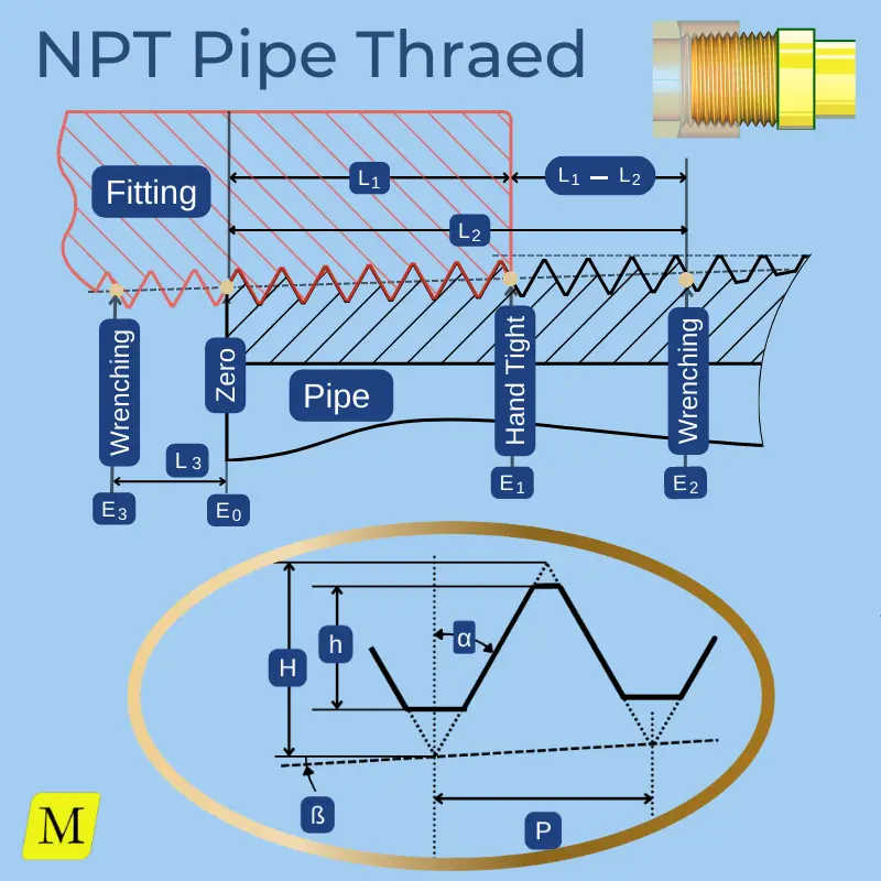
Symbols
| Symbol | Name | Explanation |
|---|---|---|
| P | Pitch | Given in TPI, and used in calculations as distance |
| ß | Thread Taper Angle |
|
| α | Thread V Half Angle (+/-) |
|
| H | Height of sharp V |
The height of the theoretical profile triangle.
\( H=\frac{\sqrt{3}}{2}\times{P} \) |
| h | Thread Height |
Distance between the truncated root and crest.
\( h=0.800\times{P} \) |
| L1 | Length of hand-tight engagement | The maximum distance that the male and female parts can be threaded by normal hand force. |
| E1 | Pitch Diameter at L1 plane | The Pitch d diameter at the plane of hand-tight engagement length (L1) of external thread (Pipe), and at the large end of internal thread (Fitting) |
| L1 - L2 | Maximum Wrenching Distance | To create a seal, the pipe and fitting should be further tightened by a wrench beyond the L1 plane. |
| L3 | Minimum Wrenching Distance |
NPT Pipe (External) Dimensions
Basic Drawing
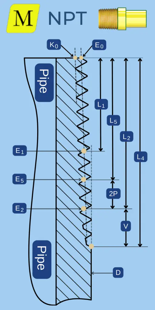
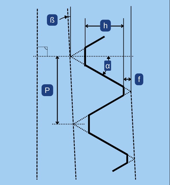
Profile Drawing
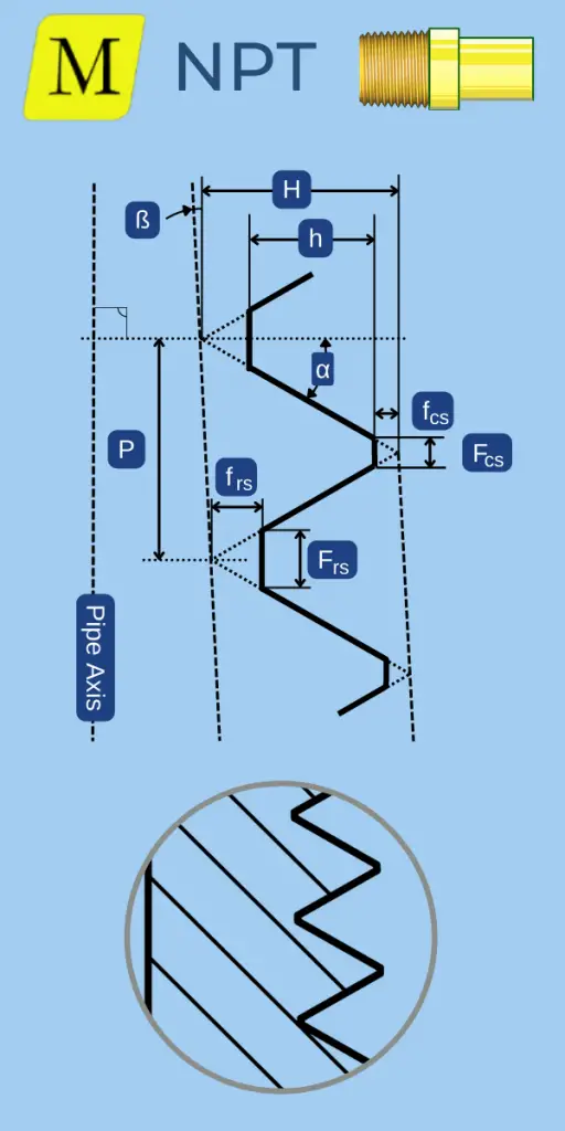
Symbols
| Symbol | Name | Explanation | ||
|---|---|---|---|---|
| D | Pipe OD | Outer diameter of the pipe | ||
| E0 | Pitch Diameter at the Pipe's end |
E0=D - (O.O5*D + 1.1 ) * P |
||
| K0 | Minor Diameter at the Pipe's end | Given as information for use in selecting tap drills. | ||
| L5 | Length of Last Complete Thread | Where the cone of the major diameter intersects the outside diameter of the pipe. From this point onward, the thread profile is not complete. | ||
| E5 | Pitch Diameter at L5 plane |
E5 = E0 + 0.0625 * L5 |
||
| L2 | Length of Last usefull Thread | Length of Last proper Thread. At L5, the thread profile starts to get truncated, but it is still considered "useful" until this point. | ||
| E2 | Pitch Diameter at E2 Plane |
E2 = E0 + 0.0625 * L2 |
||
| L4 | Thread Length (L4) | At this point, the thread disappears due to the taper angle. | ||
| V | Length of Vanish threads |
The length of "Unuseful" threads.
V = L4 - L2 |
||
Basic Dimensions Chart – NPT External Threads
NPT Fitting (Internal) Dimensions
Basic Drawing
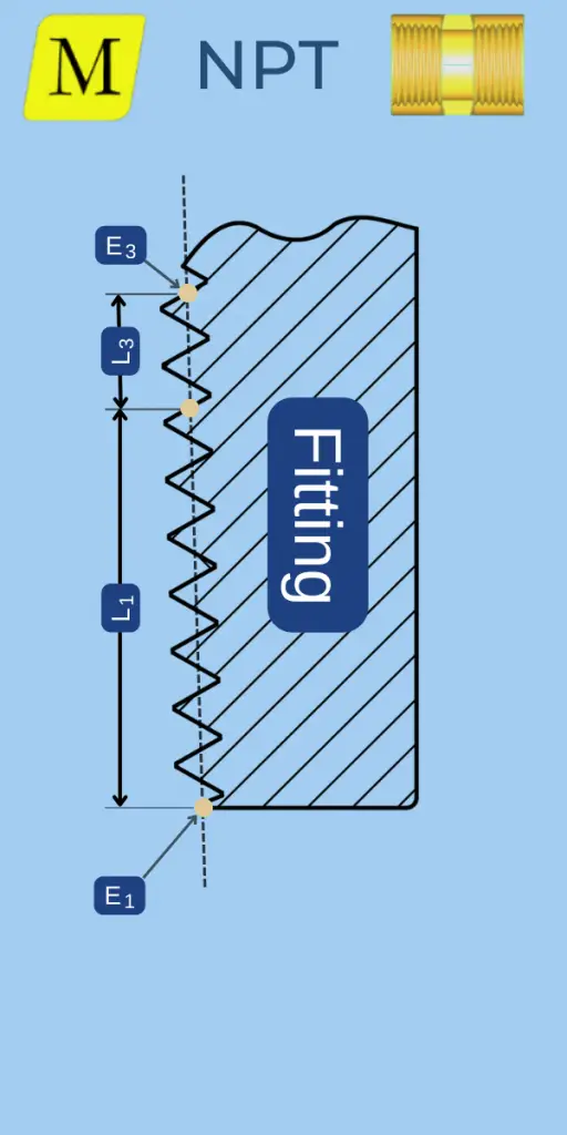
Profile Drawing
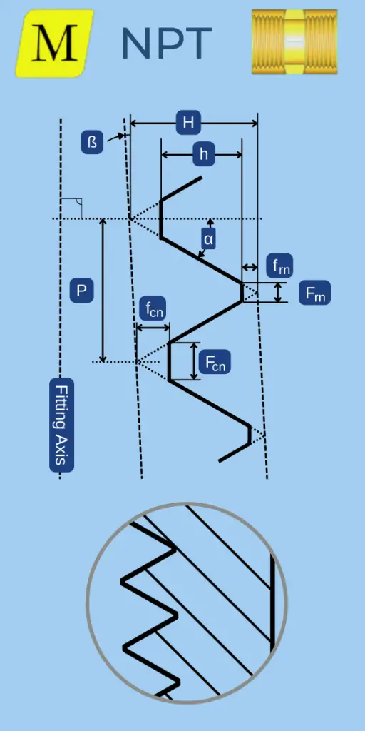
Symbols for NPT Internal (Fitting Thread)
| Symbol | Name | Explnation | ||
|---|---|---|---|---|
| E1 |
Pitch Diameter at the fitting's end |
E1 = E0 + 0.0625 * L1 |
||
| L3 | Length of Wrenching Allowance | To create a seal, the pipe and fitting should be tightened by a wrench beyond the L1 plane by a minimum distance of L3. | ||
| E3 | Pitch Diameter at the L3 Plane |
E3 = E1 - 0.0625 * (L1+L3) |
||
| L1 + L3 | Thread Length | Minimum Thread length in the fitting | ||
| T | Tap Drill Size | Recomended Drill diameter for tapping. | ||
Basic Dimensions Chart – NPT Internal Threads
Limits & Tolerances for NPT threads
The tolerancing system for NPT threads is very different and much simpler compared to Metric and Unified Inch systems. There are no tolerance classes, and the limits are either the same for all sizes or depend solely on the pitch.
Tolerances that apply to all thread sizes in the NPT series
Taper Angle (ß) Tolerance
The Angle is defined in ASME B1-20.1 as 3/4 Inch per foot. If we measure the pitch diameter at a particular location, move one foot along the axis and measure it again, we should measure a difference in diameter of 0.75″.
The tolerance is -1/16 Inch/Foot and +1/8 Inch/Foot. I have no idea why an angle is defined in such a peculiar way; however, you can convert it to degrees using the below formula:
- The linear units are measured on the diameter and the angle is measured “per side”. Therefore the 0.5 factor is applied.
The Tolerance in different units is summarized in the below table
| Unit | Nominal | Minimum | Maximum |
|---|---|---|---|
| Inch / Feet | 0.75" | 0.6875" | 0.875" |
| mm / m | 62.5 | 57.3 | 72.9 |
| Degrees | 1.7905° | 1.6413° | 2.0889° |
| DMS | 1°47' | 1°38' | 2°5' |
Lead / Pitch (P) Tolerance
- The lead should be controlled over a distance of L2 (as defined in the above charts), but never more than 1 Inch.
- Over that distance, the measured lead should be within +/-0.003 Inch/inch of the theoretical lead.
Example for 1/2-14 NPT external pipe thread:
- L2 should be 0.5337″.
- The maximum allowed variation is +/-0.5337*0.003=0.0016″ (+/-0.04 mm)
- Since the pitch is 14 TPI, this is equivalent to 14X0.5337=7.47 thread turns.
- Hence, turning the thread 7 times should advance it along its axis by 7/14=0.5″, and the allowed tolerance is +/-0.003X0.5=0.0015″.
Tolerances That Depend On The Pitch (h, f, α, and L1)
- Dimensions are in Inches.
- You can view metric dimensions in the NPT Thread Calculator.
| TPI | hmin | hmax | fmin | fmax | L1 | 2α (60°) |
|---|---|---|---|---|---|---|
| 27 | 0.02496 | 0.02963 | 0.0012 | 0.0036 | +/- 0.0370 | +/- 2.5° |
| 18 | 0.03833 | 0.04444 | 0.0018 | 0.0049 | +/- 0.0555 | +/- 2° |
| 14 | 0.05072 | 0.05714 | 0.0024 | 0.0056 | +/- 0.0714 | +/- 2° |
| 11.5 | 0.06261 | 0.06957 | 0.0029 | 0.0063 | +/- 0.0870 | +/- 1.5° |
| 8 | 0.09275 | 0.1 | 0.0041 | 0.0078 | +/- 0.1250 | +/- 1.5° |
NPSC – Internal Straight Pipe Thread
NPSC Internal Straight (parallel) Pipe Threads are used to manufacture pressure-tight fittings when assembled with an NPT external taper thread. This series applies to internal threads only. (The external thread is the standard NPT thread).
NPSC, Internal Straight Pipe Thread Dimensions Chart
- Dimensions in Inches
- The dimensions are identical to the standard internal NPT profile except for the parameters that are listed in the below chart
| Thread | Pipe | Pipe OD | Pitch (TPI) | Minor Diameter (Min) | Pitch Diameter (Range) |
|---|---|---|---|---|---|
| 1/8-27 NPSC | 1/8 | 0.405 | 27 | 0.34 | 0.3701 - 0.3771 |
| 1/4-18 NPSC | 1/4 | 0.54 | 18 | 0.442 | 0.4864 - 0.4968 |
| 3/8-18 NPSC | 3/8 | 0.675 | 18 | 0.577 | 0.6218 - 0.6322 |
| 1/2-14 NPSC | 1/2 | 0.84 | 14 | 0.715 | 0.7717 - 0.7851 |
| 3/4-14 NPSC | 3/4 | 1.05 | 14 | 0.925 | 0.9822 - 0.9956 |
| 1-11.5 NPSC | 1 | 1.315 | 11.5 | 1.161 | 1.2305 - 1.2468 |
| 1 1/4-11.5 NPSC | 1 1/4 | 1.66 | 11.5 | 1.506 | 1.5752 - 1.5915 |
| 1 1/2-11.5 NPSC | 1 1/2 | 1.9 | 11.5 | 1.745 | 1.8142 - 1.8305 |
| 2-11.5 NPSC | 2 | 2.375 | 11.5 | 2.219 | 2.2881 - 2.3044 |
| 2 1/2-8 NPSC | 2 1/2 | 2.875 | 8 | 2.65 | 2.7504 - 2.7739 |
| 3-8 NPSC | 3 | 3.5 | 8 | 3.277 | 3.3768 - 3.4002 |
| 3 1/2-8 NPSC | 3 1/2 | 4 | 8 | 3.777 | 3.8771 - 3.9005 |
| 4-8 NPSC | 4 | 4.5 | 8 | 4.275 | 4.3754 - 4.3988 |
NPTR – Railing Joint Taper Pipe Thread
The NTPR thread is used to connect Railing Joints that require a rigid mechanical connection, such as stair railings.
NPTR External Thread
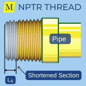
The external thread of NPTR is the same as the NPT thread except that it is shortened at the small end of the pipe. It yields a larger diameter at the end of the pipe, thus increasing its strength. This shortened thread is noticeable to the professional eye but could be overlooked by a less experienced worker.
- The shortening amount is designated by L6 and listed in the chart below.
- L6 is 3-4 times the pitch.
NPTR Internal Thread
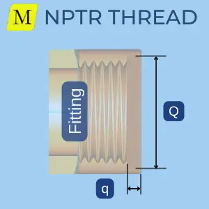
The internal l thread has the exact basic dimensions as the standard NPT thread, with a relief in the fitting’s end. It allows the external pipe thread to “disappear” when fully engaged (For cosmetic consideration).
- The diameter of the relief is designated by Q, and its depth by q.
NPTR: Dimensions Chart
- Dimensions are in Inches
- All the dimensions are the same as in the standard NPT thread chart except for the following:
- L6 – Shortening amount.
- E0 – The pitch diameter at the pipe’s end. (Replaces E1 of the standard NPT thread).
- L2, L5 & L4 should be taken from the above chart for the standard NPT thread and substructed by L6.
| Thread | Pipe OD | TPI | L6 | E6 | Q | q |
|---|---|---|---|---|---|---|
| 1/2-14 NPTR | 0.84 | 14 | 0.214 | 0.7718 | 0.86 | 0.18 |
| 3/4-14 NPTR | 1.05 | 14 | 0.214 | 0.9811 | 1.07 | 0.18 |
| 1-11.5 NPTR | 1.315 | 11.5 | 0.261 | 1.2299 | 1.34 | 0.22 |
| 1 1/4-11.5 NPTR | 1.66 | 11.5 | 0.261 | 1.5734 | 1.68 | 0.26 |
| 1 1/2-11.5 NPTR | 1.9 | 11.5 | 0.261 | 1.8124 | 1.92 | 0.26 |
| 2-11.5 NPTR | 2.375 | 11.5 | 0.261 | 2.2853 | 2.4 | 0.26 |
| 2 1/2-8 NPTR | 2.875 | 8 | 0.5 | 2.7508 | 2.9 | 0.38 |
| 3-8 NPTR | 3.5 | 8 | 0.5 | 3.3719 | 3.53 | 0.38 |
| 3 1/2-8 NPTR | 4 | 8 | 0.5 | 3.8688 | 4.04 | 0.38 |
| 4-8 NPTR | 4.5 | 8 | 0.5 | 4.3656 | 4.54 | 0.38 |
NPSM – free-fitting mechanical joints Thread
The NPSM thread series creates a non-pressure tight connection. It is mainly used in mechanical joints and special applications with no internal pressure and, consequently, no sealing requirements. It is possible to achieve a seal with the aid of an O-ring.
- The profile form is similar to that of UN threads.
- The allowance and tolerances are identical to UN threads in Class 2A for external threads and class 2B for internal threads.
- Truncation is calculated according to the below formulas:
| Root Truncation | Crest Truncation | |
| External Thread | frs=0.10825*P | fcs=0.10825*P |
| Internal Thread | frn=0.10825*P | fcn=0.21651*P |
NPSM External Thread Dimensions Chart
| Thread | Pipe OD | TPI | Pitch Diameter | Major Diameter |
|---|---|---|---|---|
| 1/8-27 NPT | 0.405 | 27 | 0.3689 - 0.3725 | 0.39 - 0.397 |
| 1/4-18 NPT | 0.54 | 18 | 0.4859 - 0.4903 | 0.517 - 0.526 |
| 3/8-18 NPT | 0.675 | 18 | 0.6211 - 0.6256 | 0.653 - 0.662 |
| 1/2-14 NPT | 0.84 | 14 | 0.7718 - 0.7769 | 0.813 - 0.823 |
| 3/4-14 NPT | 1.05 | 14 | 0.982 - 0.9873 | 1.024 - 1.034 |
| 1-11.5 NPT | 1.315 | 11.5 | 1.2311 - 1.2369 | 1.281 - 1.293 |
| 1 1/4-11.5 NPT | 1.66 | 11.5 | 1.5756 - 1.5816 | 1.626 - 1.638 |
| 1 1/2-11.5 NPT | 1.9 | 11.5 | 1.8144 - 1.8205 | 1.865 - 1.877 |
| 2-11.5 NPT | 2.375 | 11.5 | 2.2882 - 2.2944 | 2.339 - 2.351 |
| 2 1/2-8 NPT | 2.875 | 8 | 2.7526 - 2.76 | 2.826 - 2.841 |
| 3-8 NPT | 3.5 | 8 | 3.3786 - 3.3862 | 3.452 - 3.467 |
| 3 1/2-8 NPT | 4 | 8 | 3.8788 - 3.8865 | 3.953 - 3.968 |
| 4-8 NPT | 4.5 | 8 | 4.3771 - 4.3848 | 4.451 - 4.466 |
| 5-8 NPT | 5.563 | 8 | 5.439 - 5.4469 | 5.513 - 5.528 |
| 6-8 NPT | 6.625 | 8 | 6.4955 - 6.5036 | 6.57 - 6.585 |
NPSM Internal Thread Dimensions Chart
| Thread | TPI | Pitch Diameter | Minor Diameter |
|---|---|---|---|
| 1/8-27 NPT | 27 | 0.3736 - 0.3783 | 0.358 - 0.364 |
| 1/4-18 NPT | 18 | 0.4916 - 0.4974 | 0.468 - 0.481 |
| 3/8-18 NPT | 18 | 0.627 - 0.6329 | 0.603 - 0.612 |
| 1/2-14 NPT | 14 | 0.7784 - 0.7851 | 0.747 - 0.759 |
| 3/4-14 NPT | 14 | 0.9889 - 0.9958 | 0.958 - 0.97 |
| 1-11.5 NPT | 11.5 | 1.2386 - 1.2462 | 1.201 - 1.211 |
| 1 1/4-11.5 NPT | 11.5 | 1.5834 - 1.5912 | 1.546 - 1.555 |
| 1 1/2-11.5 NPT | 11.5 | 1.8223 - 1.8302 | 1.785 - 1.794 |
| 2-11.5 NPT | 11.5 | 2.2963 - 2.3044 | 2.259 - 2.268 |
| 2 1/2-8 NPT | 8 | 2.7622 - 2.772 | 2.708 - 2.727 |
| 3-8 NPT | 8 | 3.3885 - 3.3984 | 3.334 - 3.353 |
| 3 1/2-8 NPT | 8 | 3.8888 - 3.8988 | 3.835 - 3.848 |
| 4-8 NPT | 8 | 4.3871 - 4.3971 | 4.333 - 4.346 |
| 5-8 NPT | 8 | 5.4493 - 5.4598 | 5.395 - 5.408 |
| 6-8 NPT | 8 | 6.506 - 6.5165 | 6.452 - 6.464 |
NPSL – Loose-Fitting Mechanical Joints With locknuts
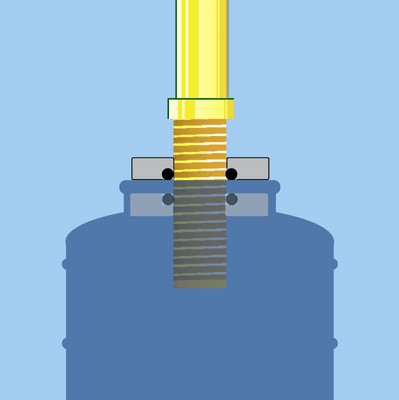
The NPSL thread series is designed to produce a pipe thread with the largest diameter possible to cut on a standard pipe. The internal and external thread dimensions are designed to have a “loose fit”, and a locknut with an O-ring is required to create a seal.
The “classic” application for the NPSL thread is connecting a pipe to a tank. The seal is achieved with two locknuts with O-rings—one on the inner face of the tank’s wall and the other on the outer face.
NPSL External Thread Dimensions Chart
| Thread | Pipe OD | TPI | Pitch Diameter | Max Major Diameter |
|---|---|---|---|---|
| 1/8-27 NPSL | 0.405 | 27 | 0.384 - 0.3805 | 0.409 |
| 1/4-18 NPSL | 0.54 | 18 | 0.5038 - 0.4986 | 0.541 |
| 3/8-18 NPSL | 0.675 | 18 | 0.6409 - 0.6357 | 0.678 |
| 1/2-14 NPSL | 0.84 | 14 | 0.7963 - 0.7896 | 0.844 |
| 3/4-14 NPSL | 1.05 | 14 | 1.0067 - 1.000 | 1.054 |
| 1-11.5 NPSL | 1.315 | 11.5 | 1.2604 - 1.2523 | 1.318 |
| 1 1/4-11.5 NPSL | 1.66 | 11.5 | 1.6051 - 1.597 | 1.663 |
| 1 1/2-11.5 NPSL | 1.9 | 11.5 | 1.8441 - 1.836 | 1.902 |
| 2-11.5 NPSL | 2.375 | 11.5 | 2.318 - 2.3099 | 2.376 |
| 2 1/2-8 NPSL | 2.875 | 8 | 2.7934 - 2.7817 | 2.877 |
| 3-8 NPSL | 3.5 | 8 | 3.4198 - 3.4081 | 3.503 |
| 3 1/2-8 NPSL | 4 | 8 | 3.9201 - 3.9084 | 4.003 |
| 4-8 NPSL | 4.5 | 8 | 4.4184 - 4.4067 | 4.502 |
| 5-8 NPSL | 5.563 | 8 | 5.4805 - 5.4688 | 5.564 |
| 6-8 NPSL | 6.625 | 8 | 6.5372 - 6.5255 | 6.62 |
| 8-8 NPSL | 8.625 | 8 | 8.5313 - 8.5196 | 8.615 |
| 10-8 NPSL | 10.750 | 8 | 10.6522 - 10.6405 | 10.735 |
| 12-8 NPSL | 12.750 | 8 | 12.6491 - 12.6374 | 12.732 |
NPSL Internal Thread Dimensions Chart
| Thread | TPI | Pitch Diameter | Min Minor Diameter |
|---|---|---|---|
| 1/8-27 NPSL | 27 | 0.3863 - 0.3898 | 0.362 |
| 1/4-18 NPSL | 18 | 0.5073 - 0.5125 | 0.47 |
| 3/8-18 NPSL | 18 | 0.6444 - 0.6496 | 0.607 |
| 1/2-14 NPSL | 14 | 0.8008 - 0.8075 | 0.753 |
| 3/4-14 NPSL | 14 | 1.0112 - 1.0179 | 0.964 |
| 1-11.5 NPSL | 11.5 | 1.2658 - 1.2739 | 1.208 |
| 1 1/4-11.5 NPSL | 11.5 | 1.6106 - 1.6187 | 1.553 |
| 1 1/2-11.5 NPSL | 11.5 | 1.8495 - 1.8576 | 1.792 |
| 2-11.5 NPSL | 11.5 | 2.3234 - 2.3315 | 2.265 |
| 2 1/2-8 NPSL | 8 | 2.8012 - 2.8129 | 2.718 |
| 3-8 NPSL | 8 | 3.4276 - 3.4393 | 3.3114 |
| 3 1/2-8 NPSL | 8 | 3.9279 - 3.9396 | 3.845 |
| 4-8 NPSL | 8 | 4.4262 - 4.4379 | 4.343 |
| 5-8 NPSL | 8 | 5.4884 - 5.5001 | 5.405 |
| 6-8 NPSL | 8 | 6.545 - 6.5567 | 6.462 |
| 8-8 NPSL | 8 | 8.5391 - 8.5508 | 8.456 |
| 10-8 NPSL | 8 | 10.66 - 10.6717 | 10.577 |
| 12-8 NPSL | 8 | 12.6569 - 12.6686 | 12.574 |


