What is G01?
The G01 command instructs the machine to move along a straight path from its current position to a new position(coordinate). The movement is performed with a controlled feederate. The new coordinate can be absolute or relative, depending on the effective mode (G90 or G91)
Syntax:
G01 X12.5 Y14.7 Z5.3 F1.2;- X, Y, Z – The target coordinate at the end of the movement.
- F – The Feedrate at which the machine will move from the current position to the target position.
What it does:
The machine will move from its current position to the target position at a controlled feederate. The endpoint position is calculated depending on the “mode” of the program:
- Cartesian or Polar coordinate mode (GCODE G15 or G16) – The default is always Cartesian.
- Absolute or Relative coordinate mode (GCODE G90 or G91) – The default depends on your controller.
Examples:
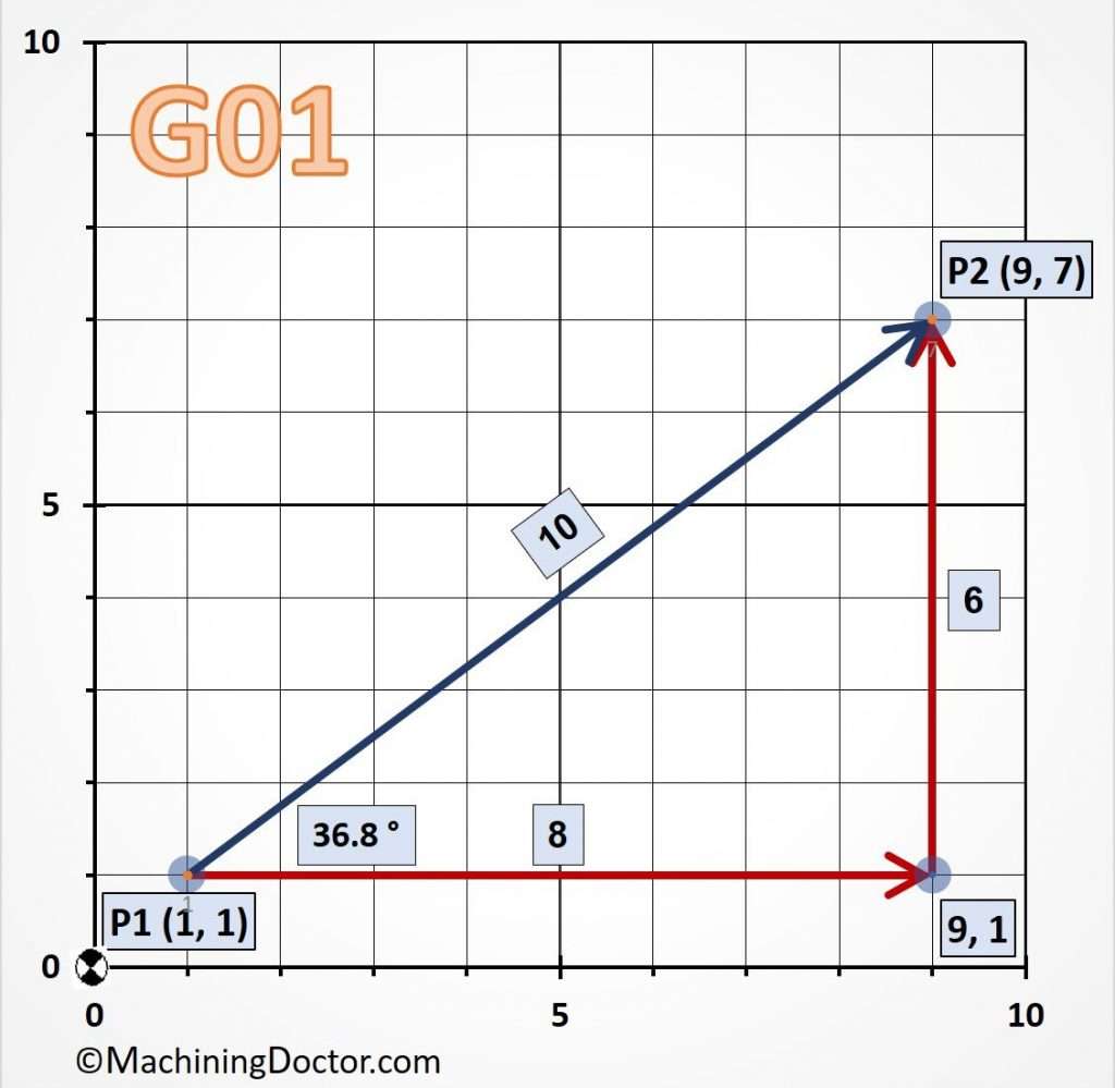
In all 4 examples, the machine will move from coordinate P1 to P2. Pay attention to the differences!

Example #1 – Move Directly from P1 to P2 along the Blue Line in Absolute Mode.
N10 G90 (Setting Absolute mode);

N20 G00 X1.0 Y1.0 (Position the machine at [P1]);

N30 G01 X9.0 Y7.0 F0.5; (Move Directly to position [P2] at a federate of 0.5);
Example #2 – Move Directly from P1 to P2 along the Blue Line in Incremental Mode.
N10 G90 (Setting Absolute mode);

N20 G00 X1.0 Y1.0 (Position the machine at [P1]);

N30 G91 (Setting Incremental mode);

N40 G01 X8.0 Y6.0 F0.5; (Move Directly to position [P2] at a Federate of 0.5);
Example #3 – Move Indirectly from P1 to P2 along the Red Lines.
N10 G90 (Setting Absolute mode);

N20 G00 X1.0 Y1.0 (Position the machine at P1);

N30 G91 (Setting Incremental mode);

N40 G01 X8.0 F0.5; (Move to Coordinate [9,1]  at a federate of 0.5);

N50 Y6.0 (Continue from [9,1] to [P2])
Important!
We can keep adding as many coordinate points as we want. The machine will continue to move to the next coordinate until the next Modal Command is encountered.
N10 G01 X9.0 Y7.0 F0.5;

N20 Y12.0 (Move to the next point in Y direction (X & Z stay the same);

N30 X5.0, Y3.0 (Move to the next point in both X and Y, Z stays the same);

N40 Z100.0; (Move to the next point in Z direction, X & Y stay the same);
And so on…
Example #4 – Move from P1 to P2 along the Blue Line with Polar Coordinates.
N10 G90;

N20 G00 X1.0 Y1.0 (Position the machine at P1);

N30 G91 (Setting incremental mode);

N40 G16(Setting Polar mode);

N50 G01 X10.0 Y36.8 F0.5 (Move from p1 a distance of 10 at an angle of 36.8 degrees and reach P2);
The result is exactly as in example #1 above!
X2 = X1 + 10 X COS(36.8) = 9.0

Y2= Y1 + 10 X SIN(36.8) = 7.0
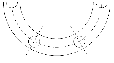
The most common use of polar coordinates is when making symmetrical features along a bore, such as a Bolt Hole Circle (BHC).
Learn about more G-Codes


