Table of Contents
Knurling Calculator
- Determines the required blank diameter for getting the correct diameter after knurling.
- Knurling Speeds and Feeds.
What is Knurling?
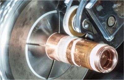
Knurling is a manufacturing operation, performed on a lathe, that copies a pattern from a knurling wheel onto a round workpiece. It is mainly used for:
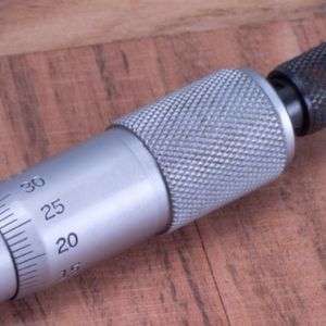
- Increasing the friction of an area on a part for easier human grip. For example, a Micrometer Knob.
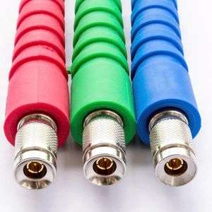
- Improving the grip of a metal part assembled into plastic. For example, electronic connectors.
- Decorative purposes.
Knurling is obtained by the displacement of material as the knurling wheel is pressed against the surface of a rotating workpiece.
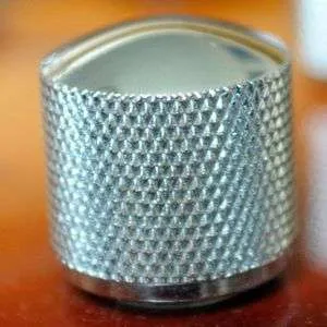
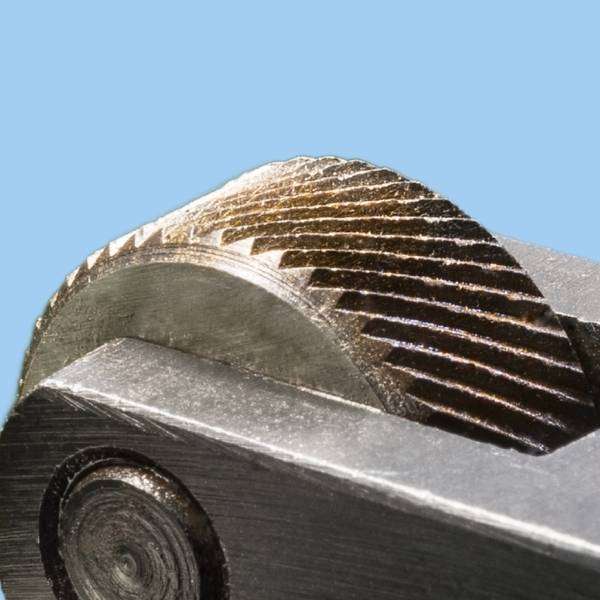

Knurling comes in 4 main patterns:
- Straight
- Diamond
- Diagonal Left
- Diagonal Right
- Unless otherwise specified Diamond and diagonal knurls are slanted 30°
There are two production technologies to obtain a knurl on a workpiece:
Knurl Forming:
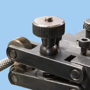
- The knurling wheel is pressed onto the rotating workpiece and displaces material.
- This method is easy to implement.
- The diameter of the workpieces changes depending on the pitch of the knurl, and the user needs to calculate the correct blank diameter to get the desired final diameter after knurling.
- The forces are high, depending on the feed, diameter, and knurl’s width.
- Low feeds.
- Suitable for small-diameter parts.
Knurl Cutting:
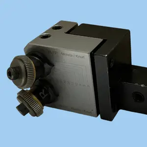
- The knurling wheels are tilted, moving along the axis of the workpiece, thus cutting instead of forming.
- The cutting tool is more expensive, and implementation is more complicated.
- No diameter change
- Smaller forces.
- Higher feeds.
- The better solution for larger diameters.
Parameters dictionary
Pitch Parameters
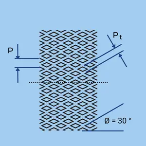
- P – Circular Pitch: The distance between teeth, measured parallel to the knurl [mm / Inch].
- Pt – Traverse Pitch: The distance between teeth, measured parallel to the workpiece/wheel axis [mm / Inc].
- TPI Tooth per Inch: The pitch expressed as the number of teeth in one inch (25.4 mm)
- Ø – Helix angle: The angle of the knurl line relative to the workpiece/wheel axis (Usually 30°)
- Z – Number of teeth.
- Tf – Tooth Factor: A factor used to calculate the number of teeth.
Diameter Parameters
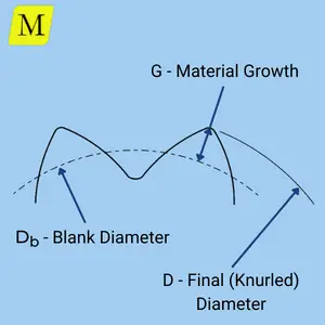
- D – Final diameter after knurling: Usually, the drawing’s requirement since it is the functional dimension of the knurl.
- Db – The blank (or turned) diameter: The required diameter on the blank that is needed to receive the final diameter after the knurling operation. This is a technological parameter that you need to calculate.
- G- Material Growth: The amount of material that is “pushed” by the knurling operation. It is an auxiliary parameter used to calculate the blank diameter.
- Dw – Wheel diameter: The diameter of the knurling wheel.
Knurling calculations
Pitch Formulas:
\( \large P_t = \LARGE \frac{P}{\cos{\theta }} \large \text { [inch / mm]} \)
\( \large TPI_t = TPI \times \cos{\theta } \)
\( \large TPI = \LARGE \frac {1}{P} \large \text { (When the pitch is measured in Inches)} \)
\( \large TPI = \LARGE \frac {25.4}{P} \large \text { (When the pitch is measured in mm)} \)
\( \large TPI_t = TPI \times \cos{\theta } \)
\( \large TPI = \LARGE \frac {1}{P} \large \text { (When the pitch is measured in Inches)} \)
\( \large TPI = \LARGE \frac {25.4}{P} \large \text { (When the pitch is measured in mm)} \)
\( \large P_t = \LARGE \frac{P}{\cos{\theta }} \large \text { [inch / mm]} \)
\( \large TPI_t = TPI \times \cos{\theta } \)
\( \large TPI = \LARGE \frac {1}{P} \)
\( \large TPI = \LARGE \frac {25.4}{P} \)
\( \large TPI_t = TPI \times \cos{\theta } \)
\( \large TPI = \LARGE \frac {1}{P} \)
\( \large TPI = \LARGE \frac {25.4}{P} \)
Diameter and tooth Formulas:
\( \large G = function (TPI) \text { [see chart and explanation below]} \)
\( \large D = D_b + 2 \times G \)
\( \large Z = T_f * TPI \times \pi \times D_b \)
\( \large T_f = function (TPI,Dw) \text { [see chart and explanation below]} \)
\( \large D = D_b + 2 \times G \)
\( \large Z = T_f * TPI \times \pi \times D_b \)
\( \large T_f = function (TPI,Dw) \text { [see chart and explanation below]} \)
\( \large G = function (TPI) \)
\( \large D = D_b + 2 \times G \)
\( \large Z = T_f * TPI \times \pi \times D_b \)
\( \large T_f = function (TPI,Dw) \)
\( \large D = D_b + 2 \times G \)
\( \large Z = T_f * TPI \times \pi \times D_b \)
\( \large T_f = function (TPI,Dw) \)
Material Growth (G) :
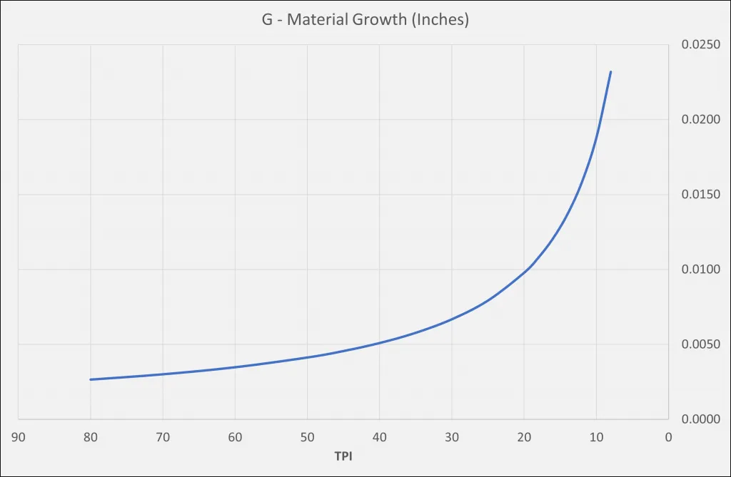
- The knurling wheel “pushes” the material when the teeth are formed, thus enlarging the diameter. Therefore, the final diameter after knurling is larger than the diameter of the blank before the knurling operation.
- The drawing of the part typically shows the final diameter after knurling.
- However, to obtain it, you need to turn the part to a smaller diameter, yielding the required diameter after the knurling operation.
- This can be done by trial and error, or by obtaining a good approximation of the Material Growth amount (G).
- G is a function of the pitch, as shown in the below chart.
- The chart is for straight knurls. For diamond-shaped knurls, the value should be increased by 15%.
- Our Online Calculator, makes all these calculations for you!
Number of Tooth Factor (Tf) :
- The number of teeth that will form on the part depends on the pitch and its diameter.
- When the pitch is given in TPI and the diameter in inches, it should equal TPI * Pi * Diameter.
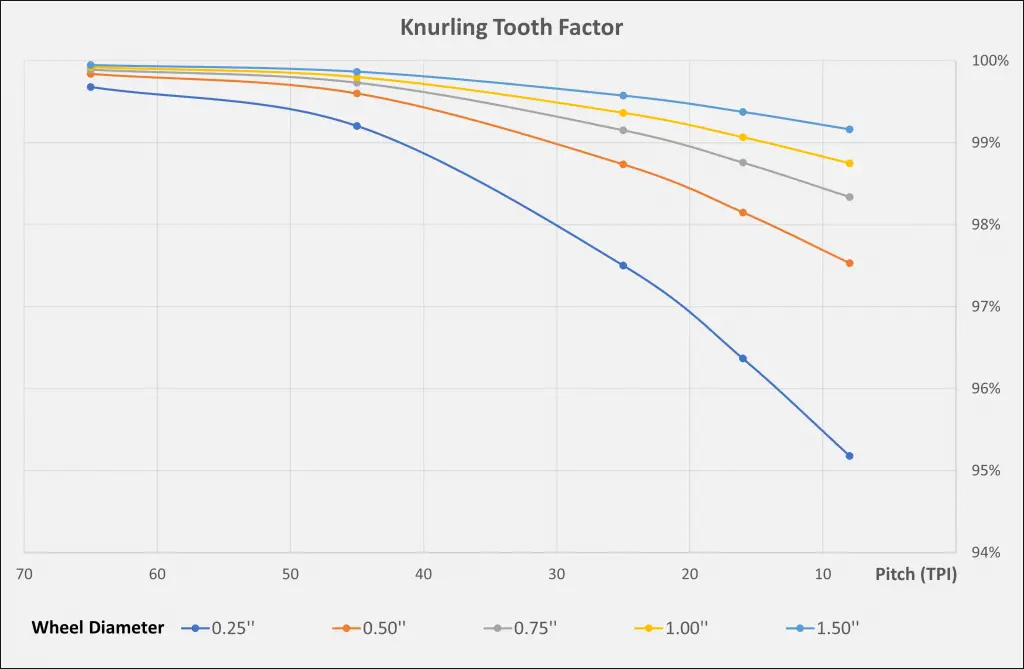
- However, in “real life”, this value should be multiplied by the Teeth Factor (TF), a function of the knurling wheel diameter and the pitch.
- The below chart shows TF values for different wheel sizes.
- As can be seen from the chart, the maximum error is 5%, and it gets smaller as the wheel diameter and the TPI increase.
- The Online Calculator implements the tooth factor automatically in its algorithm.
- The best practice is to obtain an integer number of teeth of the part. The calculator shows you the exact diameters that give such a result.
- It is recommended to use this value (as long as it is within the allowed tolerance on the drawing).
Knurling Charts
Speeds and Feeds for knurling per Material Groups
- Knurling Cutting Speeds Chart
- Knurling Feeds – Inch
- Knurling Feeds – Metric
- Knurling Pitch (TPI) Chart
Knurling Cutting Speeds Chart
Knurling Feeds – Inch
Knurling Feeds – Metric
knurling Pitch (TPI) Chart
| TPI | Pitch (Inch) | Pitch (mm) |
|---|---|---|
| 8 | 0.1250 | 3.18 |
| 10 | 0.1000 | 2.54 |
| 12 | 0.0833 | 2.12 |
| 14 | 0.0714 | 1.81 |
| 16 | 0.0625 | 1.59 |
| 20 | 0.0500 | 1.27 |
| 25 | 0.0400 | 1.02 |
| 30 | 0.0333 | 0.85 |
| 35 | 0.0286 | 0.73 |
| 40 | 0.0250 | 0.64 |
| 50 | 0.0200 | 0.51 |
| 60 | 0.0167 | 0.42 |
| 80 | 0.0125 | 0.32 |


