Table of Contents
Thread Milling G-code CNC Program Generator
Get the Gcode CNC program for your thread based on the following parameters:
- CNC Controller
- Raw material
- Thread milling tool geometry
- Thread handedness (RH / LH)
- Milling method (Climb / Conventional)
- Number of passes
- Cutting conditions
- And much more
To use the Gcode Generator effectively and get optimal results, it’s essential to have a solid understanding of the terms and theories.
Basic Thread Milling Toolpath
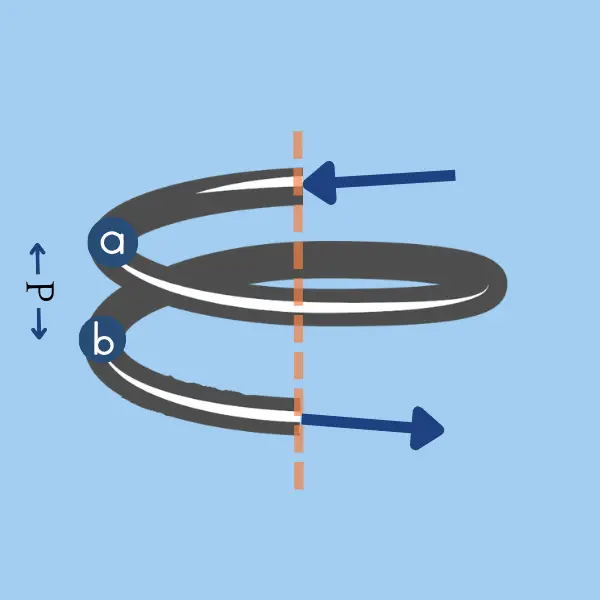
A spiral movement is required to perform a thread milling operation. Helical interpolation is a CNC toolpath along a helical path. This spiral motion combines circular movement (G02 or G03) in the XY plane with a simultaneous linear motion in the Z direction.
The Z distance from point A to B equals the pitch (Or the lead in multi-start threads).
The diameter machined by the tip of the cutting tool is the thread’s major diameter in internal threads or the thread’s minor diameter in external threads.
- Approach segment: The milling cutter moves from outside the thread until it reaches the full depth of the thread at point A. The tool path should be set so that it enters the cut tangentially.
- Threading Segment: From point A to B, the cutter moves 360 ° in a circular motion while simultaneously moving the pitch in the Z direction.
- Retraction segment: From point B, the cutter exits the material.
Below is the Gocde for an Internal M10X1 thread cut by a 5 mm thread milling tool
G03 X1.25 Y1.25 Z0.125 I0 J1.25 F251 (Approach)
G03 Z1.0 I-2.5 J0 F501 (Thread Interpolation)
G03 X-1.25 Y1.25 Z0.125 I-1.25 J0 (Retract)
Thread Milling Tool/Thread Configuration
There are three possible configurations for Tool/Thread, each with its own advantages and disadvantages, requiring a different CNC program structure.
Single Tooth
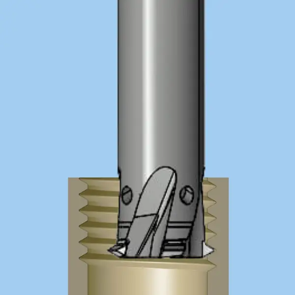
In this scenario, the tool makes a continuous toolpath, completing numerous full rotations according to the thread’s length divided by the pitch. The advantages are that less load is exerted on the tool (helps reduce vibrations) and that the tool is cheaper. The disadvantage is that this configuration yields the longest cycle time.

Gcode Example:
G03 X1.268 Y1.268 Z0.125 I0 J1.268 F253 (Approach)
G03 Z1.0 I-2.535 J0 F505 (Single Helical Interpolation)
G03 X-1.268 Y1.268 Z0.125 I-1.268 J0 (Retract)
Multi Tooth (Cutter length Longer than thread)
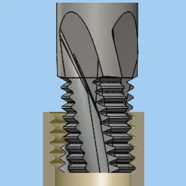
This scenario has two major advantages and is the first choice except when the load is too high. Firstly, the cycle time is the shortest, and secondly, the CNC program is the simplest. This is because the tool only needs to make a single 360° movement to complete the operation. However, it should be noted that the tool comes with a higher price tag and experiences greater loads.
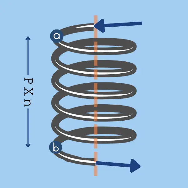
Gcode Example:
G03 X1.268 Y1.268 Z0.125 I0 J1.268 F253 (Approach)
G03 Z1.0 I-2.535 J0 F505 (Helical interpolation n times)
G03 Z1.0 I-2.535 J0
G03 Z1.0 I-2.535 J0
... n times ...
G03 Z1.0 I-2.535 J0
G03 X-1.268 Y1.268 Z0.125 I-1.268 J0 (Retract)
Multi Tooth (Cutter length Shorter than thread)
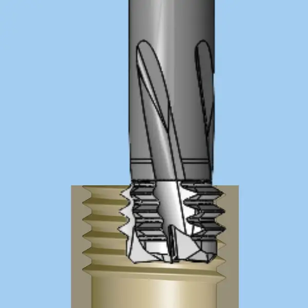
When the thread is very long, or the load is too high, it is necessary to use this configuration. However, it comes with two main disadvantages. Firstly, the CNC program becomes more complicated. Secondly, there might be a slight mismatch between iterations as the operation is not continuous.
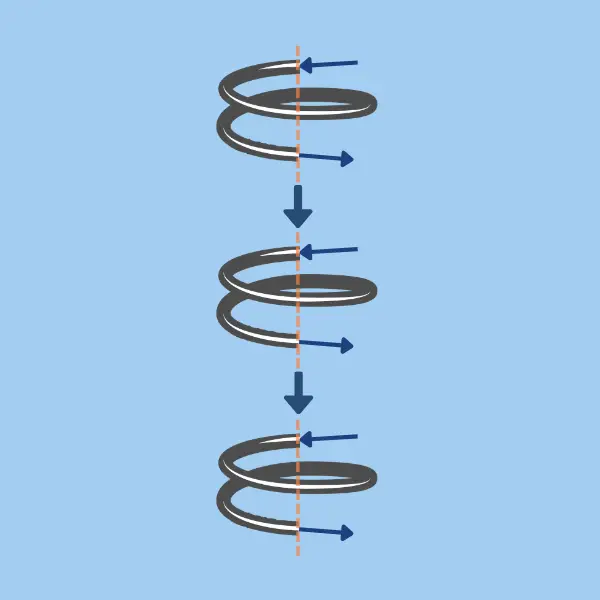
Gcode Example:
(First Cycle)
G03 X1.268 Y1.268 Z0.125 I0 J1.268 F253 (Approach)
G03 Z1.0 I-2.535 J0 F505
G03 X-1.268 Y1.268 Z0.125 I-1.268 J0 (Retract)

(Skip to next segment)
G01 G40 X-1.268 Y-1.268 F2000
G01 Z3.75

(Second Cycle)
G91 G01 G41 D1 X1.268 Y-1.268 F1003
G03 X1.268 Y1.268 Z0.125 I0 J1.268 F253
G03 Z1.0 I-2.535 J0 F505
G03 X-1.268 Y1.268 Z0.125 I-1.268 J0

(Skip to next segment)
G01 G40 X-1.268 Y-1.268 F2000
G01 Z3.75

(And so on for seveal segments)
Thread Milling Methods
Climb Milling (Down Milling)
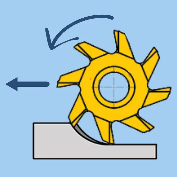
In Climb Milling, The milling moves in the same direction as the feed. It is the first choice in most thread-milling scenarios. When using this method, the thickness of the chip will start at the maximum and decrease gradually. This means that the heat generated will be transferred to the chip rather than the cutter. As a result, the wear will be slower, and the tool life will increase. The chips will be removed behind the cutter, which reduces the chance of re-cutting, which yeilds a better surface finish.
Conventional Milling (Up Milling)
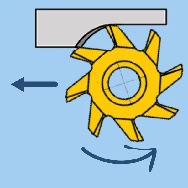
In conventional milling, the cutter rotates in a direction opposite to the feed direction. As the cutter tooth enters the material, the chip thickness starts at zero and gradually increases until it reaches its maximum size when the cutting edge exits the material. This technique generates heat in the cut area and puts a sudden heavy load on the cutter during initial contact with the workpiece. This results in faster wear and lower tool life. Moreover, the chips are carried upwards by the tooth and fall in front of the cutter, damaging the surface finish.
When to choose conventional vs climb milling?
Climb milling is the first choice for machining threads in most cases due to a lower load on the cutter, longer tool life, and better surface finish. However, there are cases in which conventional milling is the preferable way.
- If the machine does not compensate for backlash, the cutting force direction in conventional milling closes the backlash gap.
- When machining cast iron or hardened materials, because the cut begins below the material’s surface.
Thread Milling Directions
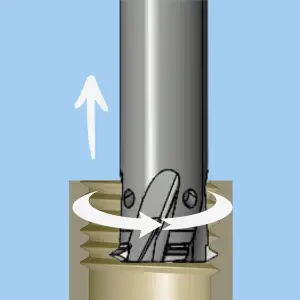
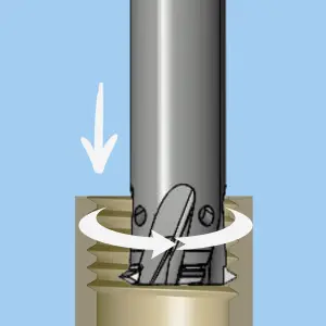
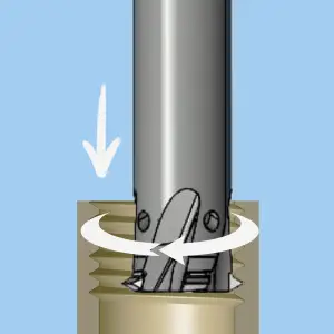
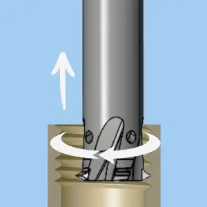
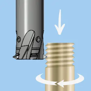
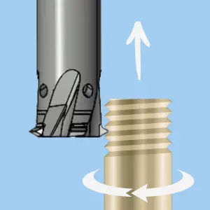
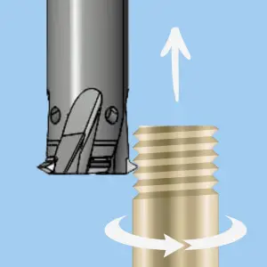
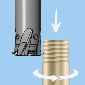
The direction of 3 movements dictates the structure of the CNC program:
- The cutter always rotates clockwise (M3).
- The helical movement of the cutter can be clockwise or counterclockwise. (G02 or G03)
- The movement in the Z direction can be from the top of the thread downwards or from the bottom upwards.
The required directions depend on 3 factors:
- The handness: Right hand or Left hand.
- Thread Type: External or Internal?
- Milling method: Climb or Conventional?
| Milling Method | Climb | Conventional | ||
| Thread Handness | Right | Left | Right | Left |
| Internal |
 |
 |
 |
 |
| External |
 |
 |
 |
 |
Entering the material (Approach toolpath)
When a thread milling cutter enters the workpiece in a straight line perpendicular to the workpiece, it may cause cutter breakage or a mark on the workpiece. To avoid this issue, it is recommended to approach the workpiece with a slow feed along a toolpath that will enter the material tangentially. This method allows the load to increase gradually, resulting in a smoother entry point with less risk of a mark on the workpiece. The same methodology should be applied on the retract toolpath when exiting the workpiece (except for the feed, which can be faster).
Internal Thread Milling

- Fast straight movement from the center along the 45° line until a safety distance from the workpiece.
- A slow, arced movement that enters the workpiece tangentially.
- The entry feed is usually set to 50% of the feed used in the thread machining.
External Thread Milling

- Fast straight movement from the center along the 45° line until a safety distance from the workpiece.
- A slow, arced movement that enters the workpiece tangentially.
- The entry feed is usually set to 50% of the feed used in the thread machining.
ThreadMill diameter selection
When a thread is turned, the resulting thread geometry is perfect. However, when thread milling is used, the nature of the process leads to a slightly distorted thread geometry. The size of the distortion depends on the relationship between the thread milling cutter diameter, the pitch, and the thread diameter.
The smallest diameter cutter will theoretically provide the most precise thread profile, but it must be balanced with the stiffness of the cutter.
Internal Thread Milling:
- A cutter diameter that is 50%-70% of the thread diameter.
- A smaller diameter also helps with chip evacuation.
- The diameter should never be more than 85% of the pre-drilled hole.
External Thread Milling:
- A cutter diameter of 70%-100% of the thread diameter.
- If profile accuracy is not an issue, a larger cutter can be used to increase productivity.
Number of Radial Passes

When the thread profile gets deeper, it is often recommended to divide the operation into multiple radial passes to reduce the load on the cutter. Increasing the number of passes can improve tool life, thread surface quality, and thread production stability, but it results in a much slower cycle time.
The right choice of depth per pass and the number of passes depend on many factors:
- Thread profile
- Workpiece material
- Tool overhang
- Number of teeth on the cutter
- Stability
- Required surface finish
Here is our recommended number of passes depending on the pitch and workpiece material. You can use it as a starting point, and adjust further according to your specific application.
| Pitch [mm] | Pitch [TPI] | Number of Passes (*) |
|---|---|---|
| Up to 1.75 | Above 14.5 | 1 |
| 1.75 – 2.5 | 10 – 14 | 2 |
| 2.5 – 6 | 4 – 14 | 3 |
| Above 6 | Below 4 | 4 |
(*) The table shows the number of passes for steel and stainless steel. For Aluminium and brass, you can use a single pass for any pitch. For Titanium and nickel-based alloys (e.g., Inconel), add 1 pass for the values shown in this table.
Converting Speed & Feed to Table Feed
In linear movements, that table feed is Vf=Fz X Z X RPM (Where Fz is the feed per tooth and Z is the number of teeth). The table feed is the feed value you need to put in the CNC program (Or provide to the CAM software)
In circular movements, the formula is more complex and depends on the relationship between the diameter of the cutting tool and the diameter of the machined element.
Internal Thread Milling
\( \large F = \frac{V_f \times \left ( \text {Thread Diameter} – \text {Cutter Diameter} \right )}{\text {Thread Diameter}} \)External Thread Milling
\( \large F = \frac{V_f \times \left ( \text {Thread Diameter} + \text {Cutter Diameter} \right )}{\text {Thread Diameter}} \)Calculating the Major & Minor Diameters for the CNC Program
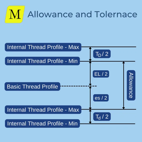
A thread’s nominal major and minor diameters represent the thread’s “Basic Profile.” However, the manufactured profile is never the “basic”. It is larger in internal threads and smaller in external threads (Otherwise, the screw will never fit on a bolt). The required size depends on the allowance and tolerance of the requested tolerance class. Therefore, the major and minor diameters also need to be shifted in the CNC program. You can use our Threading Calculator to get the dimensions for any thread in any tolerance class.
Say you have acquired the profile limits, either through our calculator or by any other means, here’s what you should do.
- You should obtain the nominal pitch diameter and its permissible limits (PD0, PDmin & PDmax) from the charts or calculator.
- After you have these figures, calculate the difference between the required and basic pitch diameter.
Internal Threads:
- When creating an internal thread, the threadmill machines the major diameter of the thread.
- The adjusted major diameter should be Dmajor + ΔPD
External Threads:
- When creating an external thread, the threadmill machines the minor diameter of the thread.
- The adjusted minor diameter should be Dminor – ΔPD
Our G-Code Generator defaults the adjusted major/minor diameters for an average thread. You can adjust further using the tool’s offset until the Go/No Go gauge passes.
