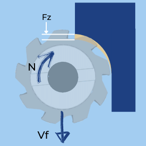
Milling Feed Rate (Also called Table Feed and Feed Speed), is the linear velocity of a milling cutter relative to the workpiece, measured in [mm/min] or [inch/min]. It is calculated by:
- Multiplying the Feed per Tooth by the Number of Teeth and then by the Spindle Speed.
- Multiplying the Feed per Revolution by the Spindle Speed.
It is the actual parameter that is input into the machine as the feedrate. The table feed is not specific for an application or cutter, and it needs to be calculated based on the Chip Load, Cutter Geometry, Radial Depth of cut, and Cutting Speed.
Table Feed Basic Formulas
\( \large \unicode{86}_f= F_n \times n\)
\( \large \unicode{86}_f= F_z \times Z \times n\)
\( \large \unicode{86}_f= F_z \times Z \times n\)
Vf- Table Feed [mm/min or Inch/min]
Fn- Feed per revolution [mm/rev or Inch/rev]
Fz- Feed per Tooth [mm/tooth or Inch/tooth]
n- Spindle Speed [RPM]
Fn- Feed per revolution [mm/rev or Inch/rev]
Fz- Feed per Tooth [mm/tooth or Inch/tooth]
n- Spindle Speed [RPM]
How to calculate the Milling feed Rate from the basic data?

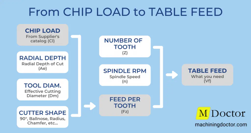
To calculate the Milling Feed Rate you will need first to prepare the following basic data:
- Cutter Shape [90°, Ballnose, Chamfaring, Round, etc]
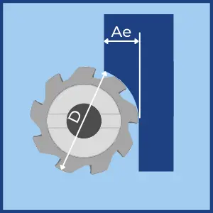
- Cutter Diameter [D] – If you are using a shaped cutter (Non 90°), take cato use the Effctive Cutter Diameter.
- Number of Tooth [Z]
The user always knows the above three.
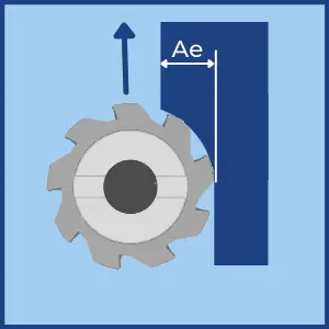
 Radial Depth of Cut [Ae] – Depends on how you plan to prefoprm your application.
- Cutting Speed [Vc] – Get wit with our Speeds and Feeds Calculator or from the tool supplier’s catalog/website.
- Chi pLoad [CL] – Get wit with our Chip Load Calculator or from the tool supplier’s catalog/website.
Whith the above parmeters you can proceed to calculate the Milling Feed (Table Feed)
- Calculate the Chip Thinning factors in order to get the Feed per Tooth.
The Chip Thinning factors make sure that the actual Feed per Tooth [Fz} will maintain the desired Chip Load according to the tool geometry and application settings. - Radial Chip Thinning Factor [RCTF] –
Radial chip thinning factor should be implemented with the Radial Depth of Cut [Ae] is smaller than the cutter’s radius. (When Ae is bigger the factor is 1). At very small Ae the factor can be up to 3 times!
Radial Chip Thinning factor calculation:

\( \large RCTF = \)
\( \huge \frac{1}{\sqrt{1-\left ( 1 – 2 \times \frac{Ae}{D} \right )^{2}}} \)
\( \huge \frac{1}{\sqrt{1-\left ( 1 – 2 \times \frac{Ae}{D} \right )^{2}}} \)
- Aproach Angle Chip Thinning Factor [ACTF] –
The Aproach Angle Chip Thinning factor should be implemented when the cutter is not a standard 90° shape (For example a Ballnose or Chamfaring cutter).
Chip Thinning factor for Chamfer/feed miiling cutters:

\( \large ACTF = \)
\( \huge \frac{1}{\sin({K_{apr})}} \)
\( \huge \frac{1}{\sin({K_{apr})}} \)